Bill of materials (BOM)
Chassis
| Item Name | Quantity | Notes | Image |
|---|---|---|---|
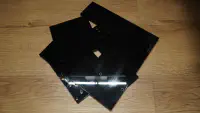
| LGDXRobot2 Chassis Plates | 1 | The instructions are provided on the next page. |
 |
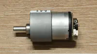
| GM37-520 DC Gear Motor (12V) | 4 | A gear ratio of at least 1:90 is recommended to ensure sufficient torque. The motor must include an encoder, and the connector type is PH2.0. |
 |
| Mounting Bracket for 37mm DC Gear Motor (with screws) | 4 | These brackets are sometimes included when purchasing the motor. |
 |
| Mecanum Wheel Set | 1 set (4 wheels) | It is recommended to choose wheels with a 75–80 mm diameter and 32+ mm width. The coupler must be 6 mm to fit the motor shaft. |
 |
| M4 Screws (12 mm length) | 44 | Only 20 screws must be exactly 12 mm in length; Longer screws may be used for the remaining 24 screws. |
 |
| M4 Nuts | 18 | — |
 |
| M4 Standoffs (70 mm) | 8 | — |
 |
| M4 Standoffs (35 mm) | 4 | — |
 |
Controller Board
| Item Name | Quantity | Notes | Image |
|---|---|---|---|
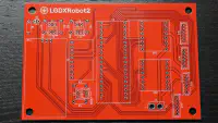
| LGDXRobot2 Controller Board | 1 | The instructions are provided on the next page. |
 |
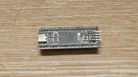
| BlackPill (STM32F411CEU6) | 1 | Official GitHub (not an affiliate link) |
 |
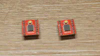
| TB6612FNG Module | 2 | — |
 |
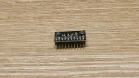
| ICM-20948 | 1 | Must be V1 as the pins of V2 is not compatible with the controller board. |
 |
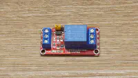
| Relay Module | 1 | Triggers when the input is high. |
 |
| 3.5 mm Red LED | 1 | — |
 |
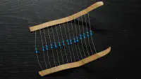
| Resistor (220 Ω) | 1 | — |
 |
| Resistor (10 kΩ) | 3 | — |
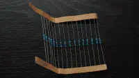 |
| Resistor (68 kΩ) | 3 | — |
 |
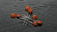
| Capacitor (0.1 µF) | 3 | — |
 |
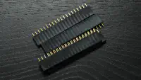
| 2.54 mm (0.1 inch) Header Strip (Female) | Suitable | — |
 |
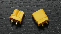
| XT30 Connector (Male & Female) | 1 | Optional for soldering wires onto the board. |
 |
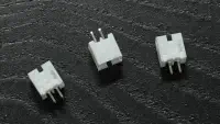
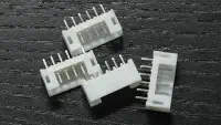
| PH2.0 2P Connector (Female) | 3 | — |
 |
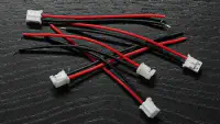
| PH2.0 2P Cable (Male) | 3 | — |
 |
| PH2.0 6P Connector (Female) | 4 | — |
 |
| PH2.0 6P Cable (~15 cm) | 4 | The keys face opposite directions. |
 |
Power Supply
| Item Name | Quantity | Notes | Image |
|---|---|---|---|
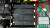
| 18650 Battery | 8 | — |
 |
| 18650 Battery Holder | 2 | 4 batteries in series. |
 |
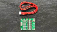
| 18650 Battery Protection Board | 2 | Optional |
 |
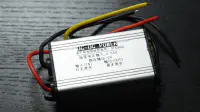
| 12V DC-DC Buck Converter | 1 | For the motors. |
 |
| 5V / 12V DC-DC Buck Converter. | 1 | For the onboard computer, choose the voltage that matches the input voltage of the computer |
 |
| DC Power Jack / USB Cable | 1 | Depends on the power input for the computer. | — |
A custom power supply may be designed, but note that the motor voltage is 12 V.
Miscellaneous
| Item Name | Quantity | Notes | Image |
|---|---|---|---|
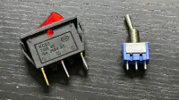
| Emergency Stop Button | 1 | — |
 |
| Power Switch | 1 | — |
 |
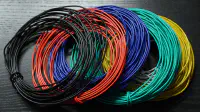
| Cables | Suitable length | — |
 |
Onboard Computer
Either the NUC setting or the Single Board Computer (SBC) setting may be chosen.
NUC
| Item | Quantity | Notes |
|---|---|---|
| NUC | 1 | Only Slim Kit is supported. (37mm height) |
| M3 Screws (10 mm length) | 2 | — |
SBC
| Item | Quantity | Notes |
|---|---|---|
| Raspberry Pi or NVIDIA Jetson Nano | 1 | — |
| M2.5 Screws (8 mm length) | 4 | — |
| M2.5 Standoffs (16 mm) | 4 | — |
Sensors
| Item Name | Quantity | Notes | Image |
|---|---|---|---|
| RPLIDAR A1 or C1 | 1 | — |
 |
| M2.5 Screws (8 mm length) | 4 | — | |
| Camera | 1 | Optional, it was originally designed for the Realsense D435, but any camera that can be fitted in the chassis is acceptable. | |
| 1/4-Inch Tripod Screw | 1 | Optional |
 |
Tools (Not installed on the robot)
| Item |
|---|
| Hex Key Set |
| 7 mm Wrench |
| Crosshead Screwdriver |
| Soldering Iron |
| Solder Paste |
| Hot Glue Gun / Strong Double Sided Tape |
Notes for the Onboard Computer
The minimum requirement for the onboard computer is a Raspberry Pi 5 4GB. It is capable of running SLAM on Nav2 with the RViz GUI, as well as computationally intensive Nav2 plugins. The recommended screen resolution is 1920 × 1080. Please refer to this video for instructions on using a custom power supply with a Raspberry Pi 5.
The power supply listed here is for stepping down to 12V / 5V. If the onboard computer is powered by 19V, the component should be modified, for example by using a step-up converter.
Although the Raspberry Pi 4 or Nvidia Jetson Nano (older version) can technically be used, this is not recommended due to insufficient computational power. The robot’s movement is jittery.